How to Replace a Flow Inducer Fan Motor in a Gas Furnace
My furnace was making a horrendous buzzing sound when I turned on the heat. The awful sound reverberated throughout the house; it was terrible! The problem ended up being a failing flow inducer motor.
In this post I document the steps to remove the old one and install a new flow inducer motor assembly for a gas furnace. I hope this helps someone out there!
This project is very straightforward and takes about an hour.
Failing Flow Inducer Motor
Question: How do you know if your flow inducer motor is failing or has failed?
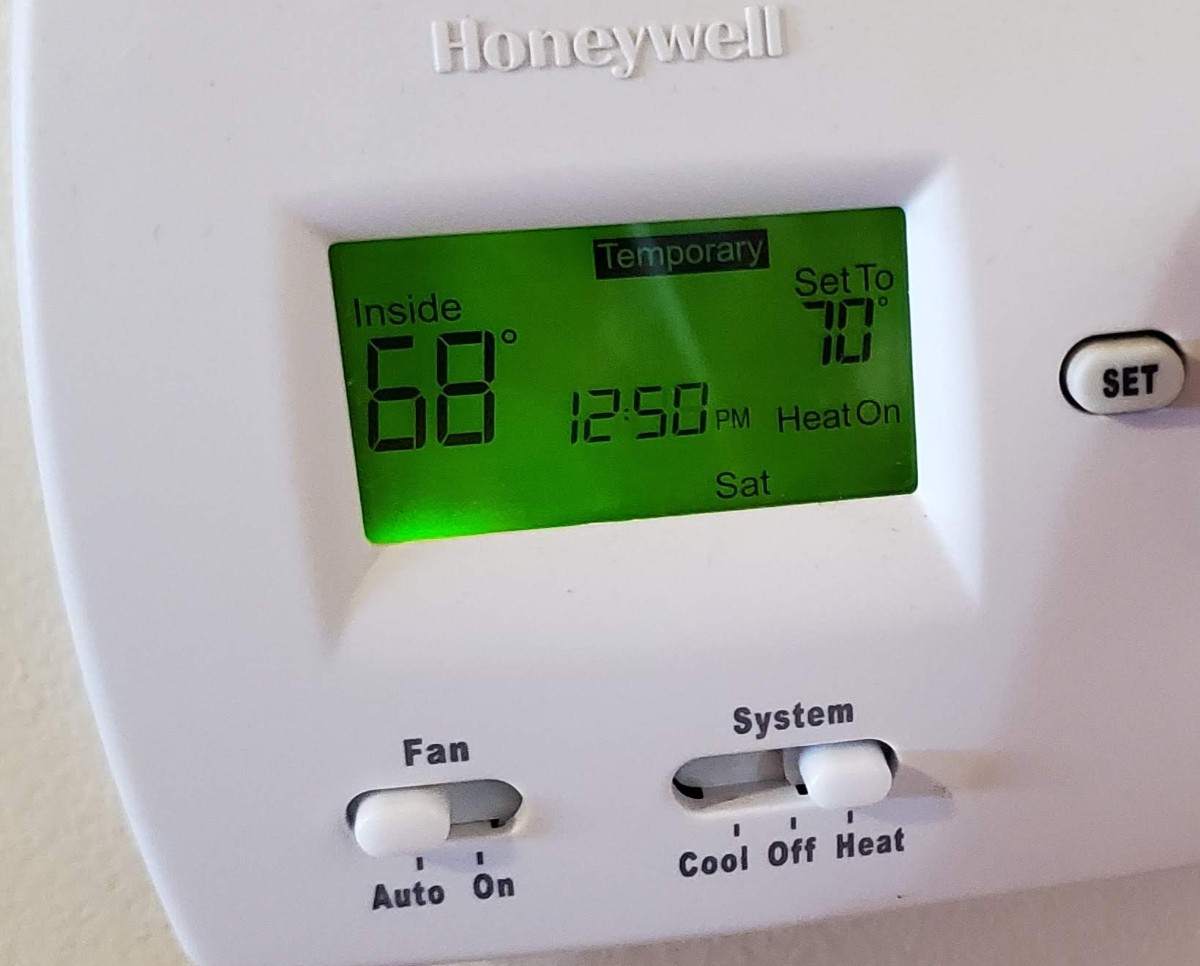
Answer: When you turn on the furnace (set your thermostat to ‘heat’ and increase the temperature set point above the current temperature), and you hear a loud buzzing sound. The sound may be intermittent. This indicates that the flow inducer motor is failing.
Another indication of a failed flow inducer motor is when you turn on the heat and no hot air comes out! This may mean that your flow inducer has failed completely.
For me, the problem was a motor that was in the process of failing. It is a bit hard to describe the sound that it was making, so here is a link to a video showing the sound of the failing motor and the sound of the new motor.
If you buy through links on this site, I may earn an affiliate commission – at no cost to you.
Have you determined that your furnace blower motor is actually the culprit? Check out this post on replacing your furnace blower motor!
Tools and Supplies Needed for this Repair
- Flat Screwdriver (or 1/4″ hex driver)
- Phillips Screwdriver
- Rag
- Flow Inducer Motor
- High Temperature RTV Sealant
- Pliers
- knife or razor blade
Identifying the Correct Part Numbers
The model number of my furnace was a Carrier 58MCB as indicated by the installation manual.

Other furnace models that this guide apply to include:
340MAV, 340AAV, 345MAV, 350MAV, 351DAS, 353AAV, 490AAV, 58MCA, 58MCB, 58MEB, 58MSA, 58MXA, 58MXB, PG9MMA, and PG9MAB.
The failing motor itself had this information listed on it:
YDZ-040L22541-01 and HC28CQ116
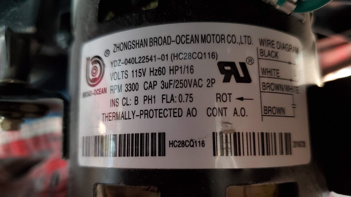
While I did find the YDZ-040L22541-01 available on Amazon, it was quite expensive.
I ended up going with the Packard Draft Inducer Fan Furnace Blower Motor for Carrier 1179081 320725-756. Which ended up being an exact drop-in replacement for what was in the furnace originally. This is the information printed directly on the fan motor of the new flow inducer fan assembly.

Step-by-Step Guide for Fixing a Failed Flow Inducer Motor
The following pictures and steps walk through the process I used to swap out the flow inducer motor assembly. As always, if you are unsure what you are doing, please consult and expert.
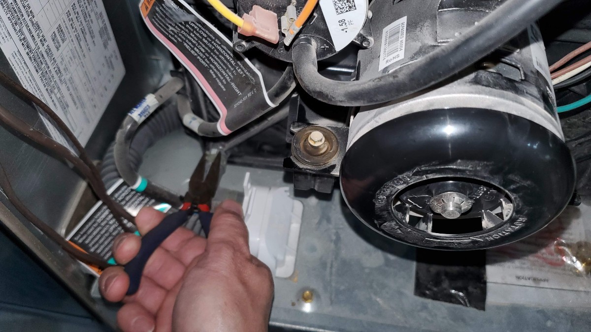
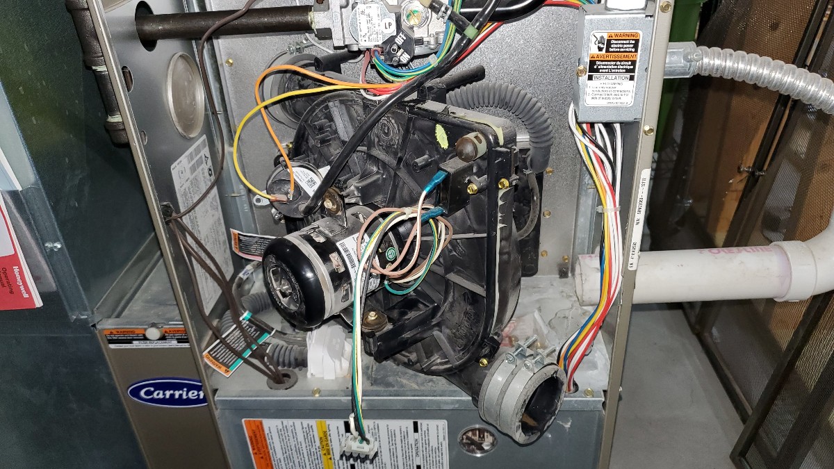
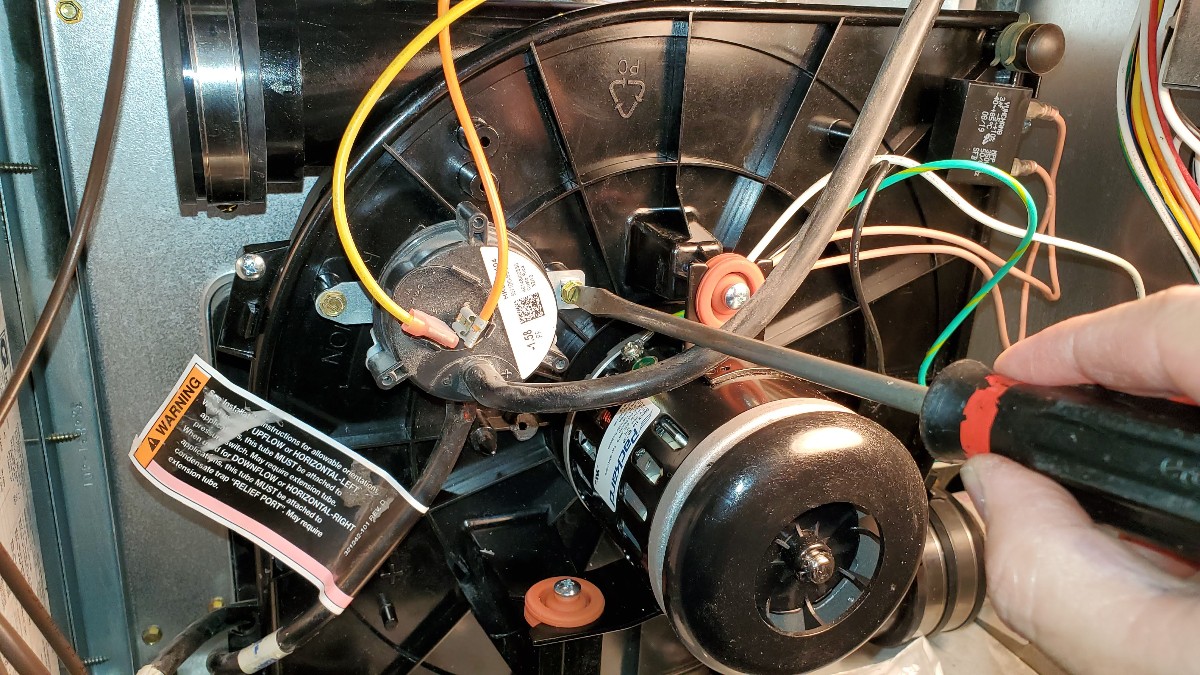
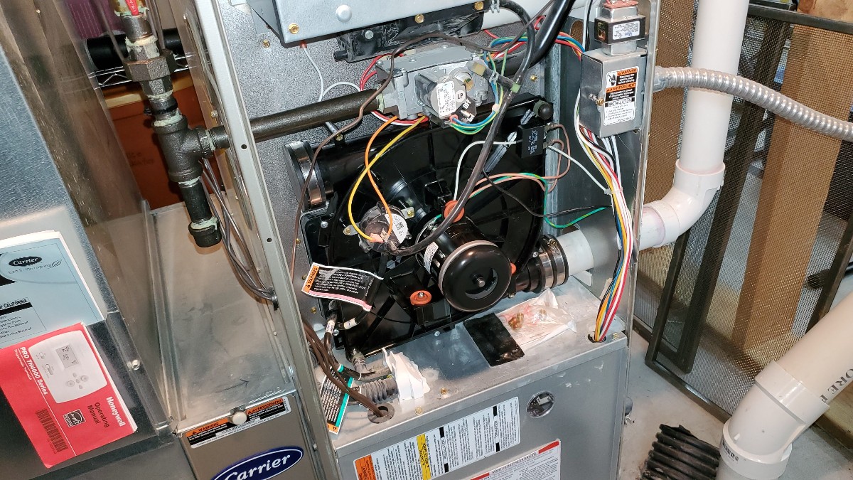
First, open the access panel to reveal the flow inducer motor assembly. Take a picture of what you are dealing with. When you are done, you can compare the new to the old and check your work to make sure you didn’t miss something…

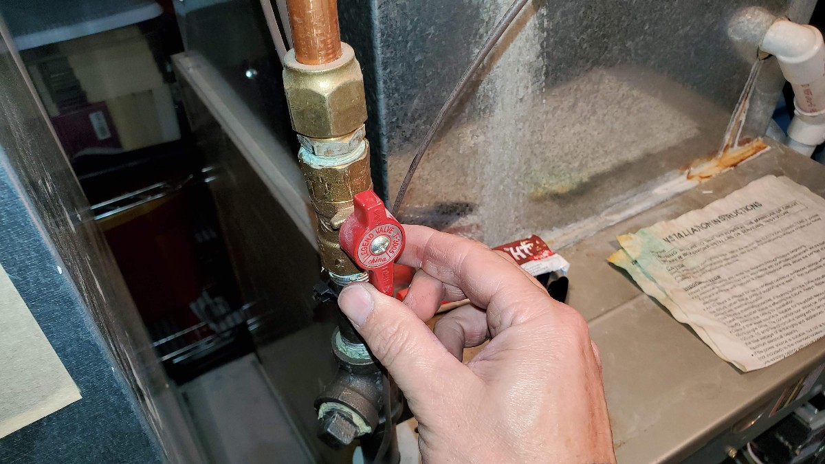
Locate the gas valve and turn off the gas to the furnace.

Turn off the power to the furnace. Yours may have a switch. I turned off the power at the circuit breaker.

Inside the access panel, unplug the power to the inducer motor. It is a white plastic clip. Press the tabs on both sides to release the clip.

The flow inducer motor assembly is mounted by 4 screws, 2 on the top and 2 on the bottom. Use a flat screwdriver or 1/4″ hex driver to remove these 4 screws.

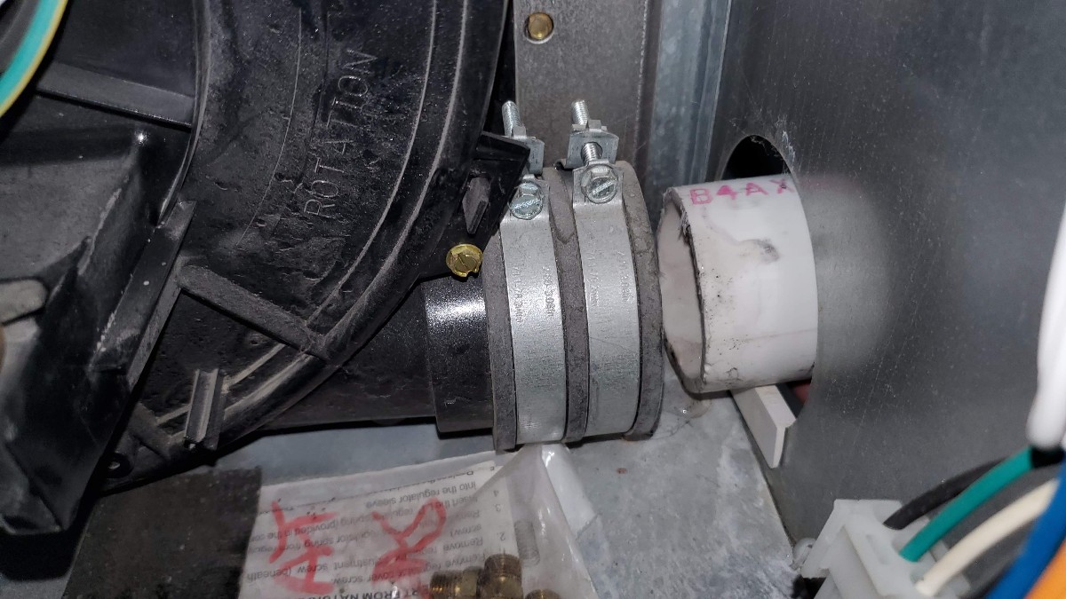
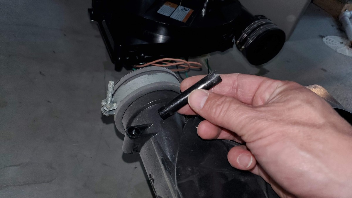
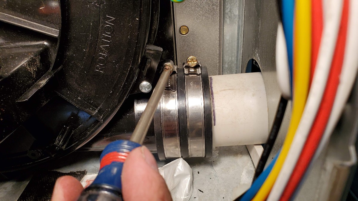
Next, use some tape or a marker to mark how far the exhaust tube is pressed into the fan assembly. You will use this mark to know how far to push it in after you have installed the new motor.

Use a flat screwdriver to loosen the clamps.

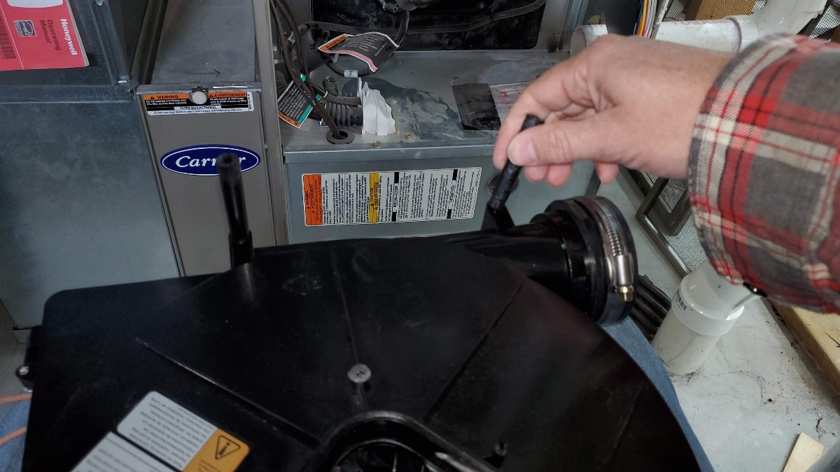
Then pull the exhaust tube out of the assembly.
For added security, turn off the gas switch near the top of the unit, as well.

There is a pressure switch that makes sure your unit is working and actually drawing a vacuum. You will re-use this switch. Unscrew it from the assembly using a flat screwdriver. Remove the 2 screws.

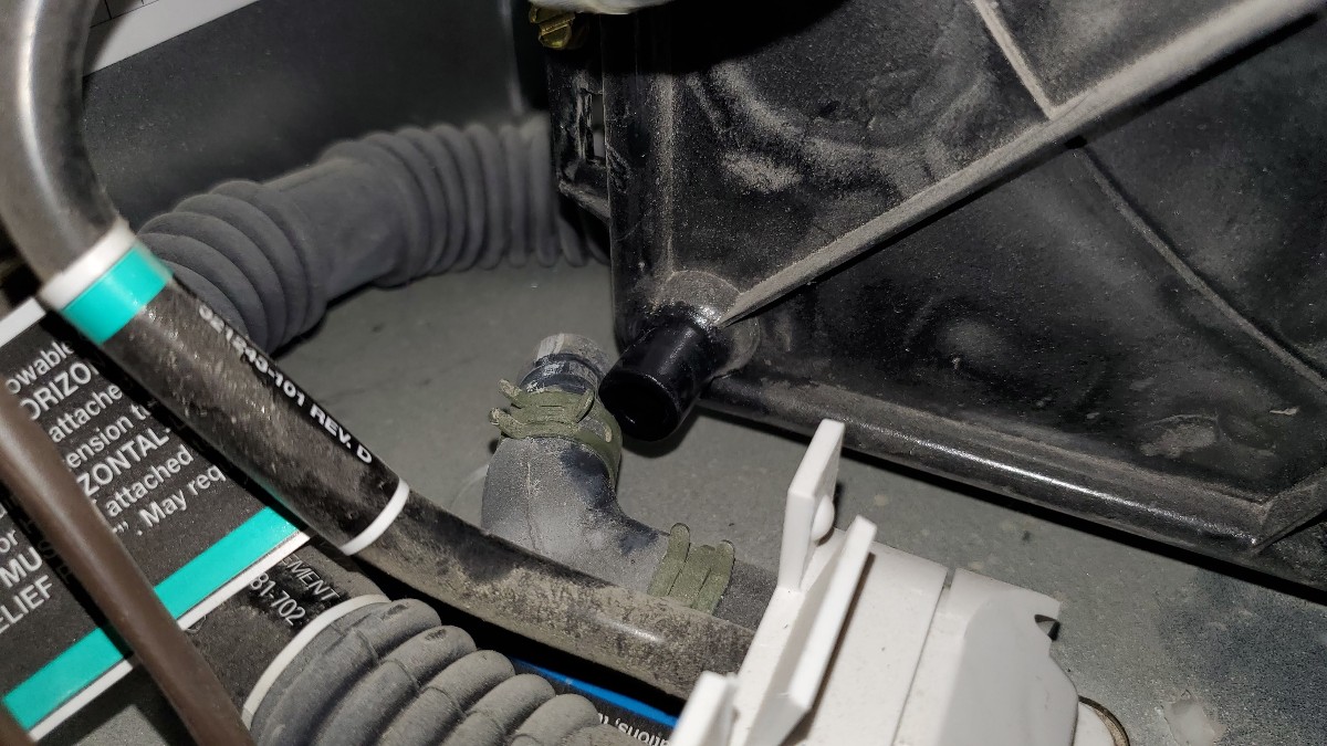
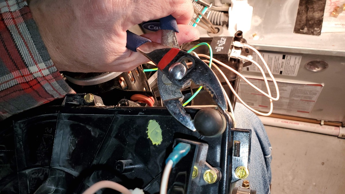
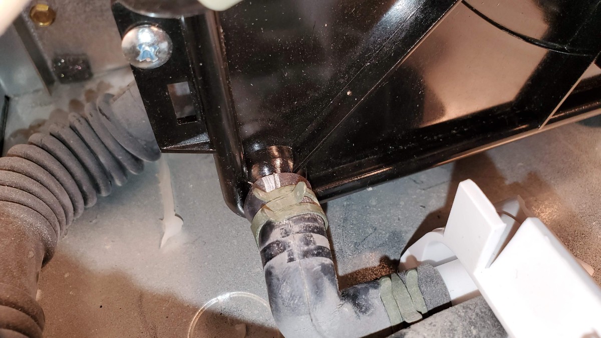
Use a pliers to disconnect the drain hose from the bottom of the assembly.
Leave the hose disconnected for now.
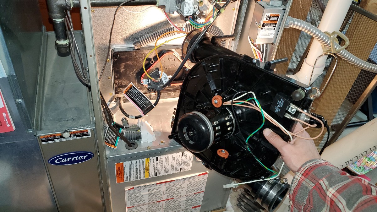
You are now ready to remove the old assembly. It is sealed in place with some silicone sealant, so if it does not come off right away, give it steady pressure and pull it outward.

Then feed the assembly out around all of the wires. Note the position of any tubes behind the unit as you remove it.
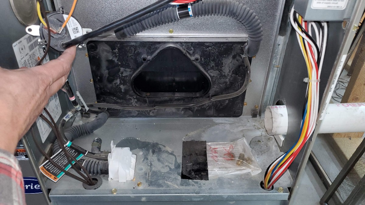
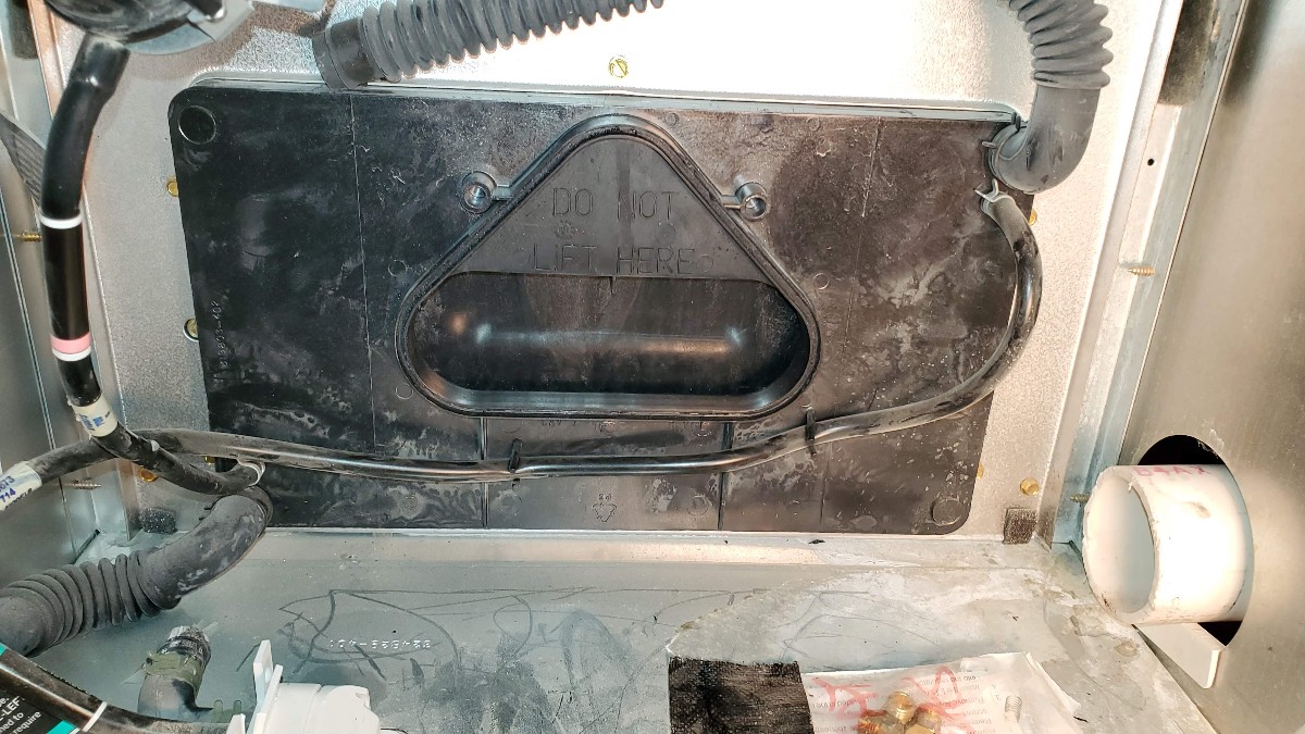
This is what the space looks like with the assembly removed, showing the exhaust port.
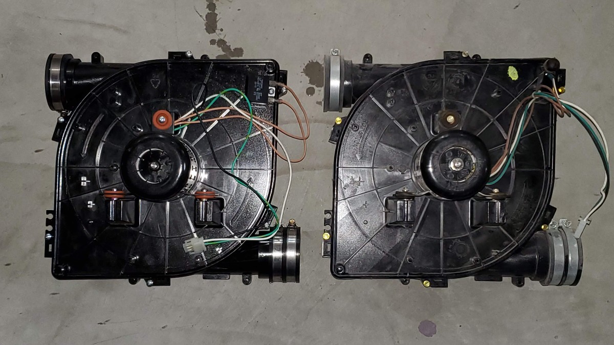
Here are a few pictures of the old and new flow inducer motor assemblies side by side. Backside of the units (old on the left):
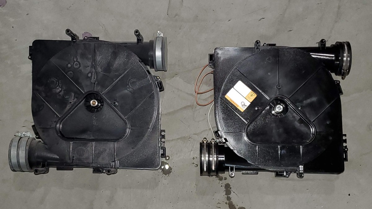
Front of the units (new on the left):
The 4 mounting screws have spacers. Remove the 4 plastic spacers from the old unit. They are press-fit in, so give them a good tug.
Press-in the spacers into the new unit.
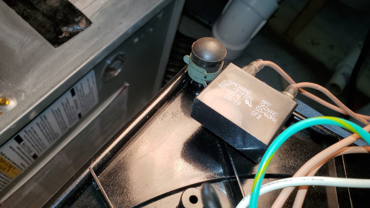
There is also a plug on the old unit near the top. Use a pliers to remove it.
And transfer the plug to the new unit.
I found that there was some dirt and dead bugs in the exhaust port. If this is the case for you, clean it out with a vacuum.

The triangular exhaust port has a groove where the old sealant was. Use a knife, razor blade, or screwdriver to scrape out the old sealant.
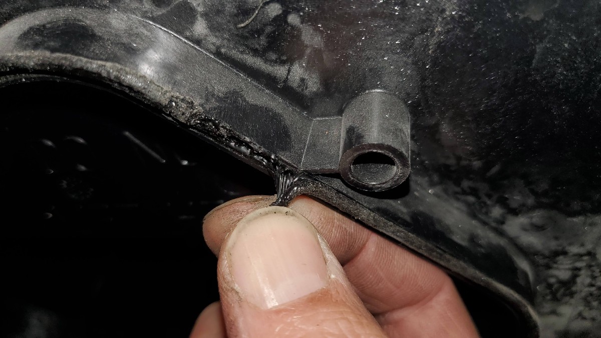
Here is the exhaust port with the old sealant removed.
Use a high temperature RTV sealant.

Put a bead of the silicone sealant into the groove. Alternatively, put the sealant onto the new assembly, whichever you find easier.

Carefully thread the new motor assembly in amongst the wires and into place.
Make sure there are no wires caught between the exhaust port and the new assembly. Reach around behind and verify that the triangular assembly port has nested properly into the exhaust port groove. Alternatively use a small mirror if you cannot reach back there because it is too tight.
Re-use the long screws. Insert and the 4 screws loosely at first to make sure you can get them all started. Once they are all started, tighten them down. Recall there are 2 at the top.

And 2 screws along the bottom.

Next, re-attach the pressure gauge using the 2 screws you removed earlier.
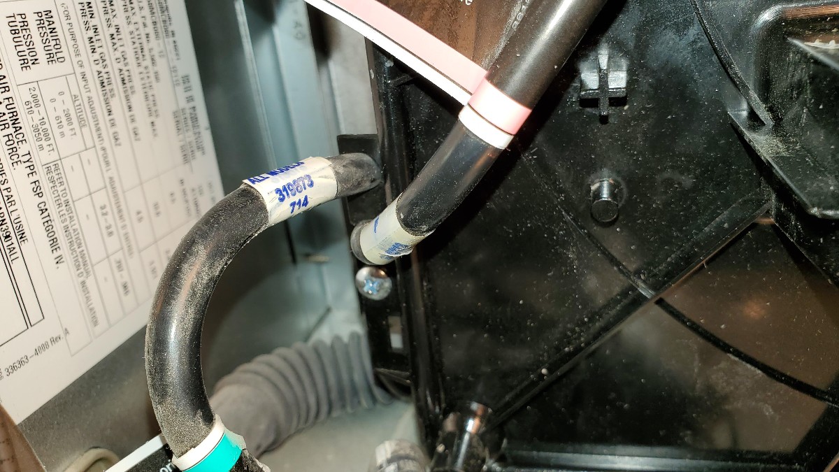
Press the pressure tubes into the grooves alongside the edge of the assembly.
Use a pliers to re-attach the drain tube.
Plug in the white plastic connector that supplies power to the unit.

Push the exhaust tube into the assembly up to the line that you made earlier. Tighten up with clamps with a screwdriver.
The new flow inducer motor assembly is now installed. Look at the picture that you took of the original unit, and verify that everything is connected and the same as it was previously.

Remove all tools from the chamber.
Remember to turn the gas switch back to the “on” position.

When you are sure everything is connected properly, turn on the power to the unit.

Turn on the gas line.
To test out the system, set your thermostat to the “Heat” setting and turn up the “set to” temperature.
Verify that the flow inducer fan is spinning properly and that heat is coming out of the vents.
Put the access cover back on.
I hope this picture guide was helpful for someone out there. I was unsure which motor assembly to buy, and this one worked perfectly for me. I hope that it works out for you too.
Tools and Supplies Used for this Repair
- Flat Screwdriver (or 1/4″ hex driver)
- Phillips Screwdriver
- Rag
- Flow Inducer Motor
- High Temperature RTV Sealant
- Pliers
- knife or razor blade


Thank you !